High-Speed Flexographic Printing Press Control System
This application case covers the synchronization and commissioning of AC inverters and AC servos for a central impression (CI) flexographic printing press.
System Architecture Overview
Component | Equipment Type | Control Mode | Interface / Protocol |
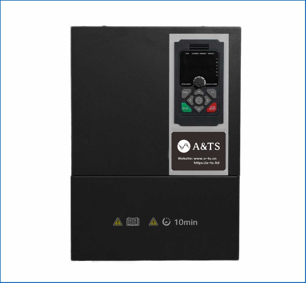
Main Impression Cylinder | High-Power Inverter 30kW | Closed-Loop Vector Control | Analog / Fieldbus |
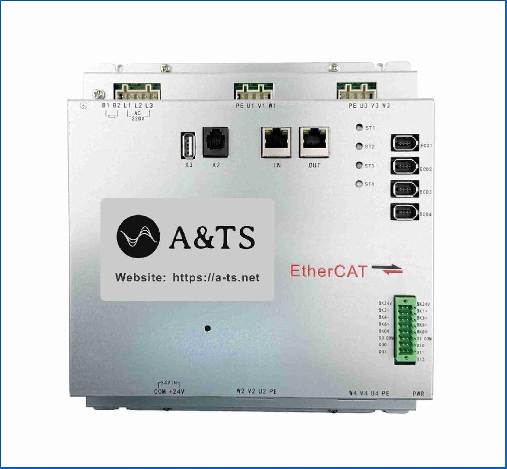
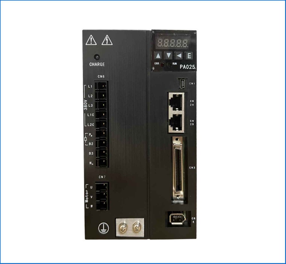
Print Station Plate Cylinders (x4) | High-Dynamic Servo Drives (3.5 kW) | Shaftless Electronic Gear / Cam | EtherCAT (CoE / SOE) |
Infeed / Outfeed Nip Rolls | Servo Drives (2.2 kW) | Speed / Torque Control | Fieldbus Motion Control |
Unwind / Rewind Stations | Vector Inverters (7.5 kW) | Closed-Loop Tension Control | Analog / Fieldbus |
Inverter Commissioning (Unwind / Rewind & Central Drum)
Printing presses demand continuous web tension to prevent color misregistration, substrate stretching, or material tears.
1. Main Drive (Central Impression Drum) Setup
Control Mode: Closed-loop vector with high-resolution encoder feedback (e.g., 23-bit absolute).
Speed Regulation: Must hold speed fluctuation below 0.01% at maximum line speeds (300-500min). Set long acceleration ramps (15-30s) to prevent dynamic jerk from shifting tension.
2. Tension Control Inverter Setup (Unwind / Rewind)
Parameter | Recommended Setting | Rationale |
Control Mode | Closed-Loop Torque Control with Dancer / Load Cell | Direct torque adjustment based on active feedback |
Diameter Calculation | Line Speed / Angular Speed ratio | Automatically adjusts motor output torque as roll diameter changes |
Tension Reference | 10-50 N/m (Substrate Dependent) | Maintains constant web stress; set lower for thin PE films, higher for paperboard |
Inertia Compensation | Dynamic Friction + Acceleration Torque Compensation | Prevents tension spikes or slack during emergency stops or speed ramps |
3. Tuning & Testing Procedure
Perform Static & Dynamic Motor Autotuning without load to populate stator/rotor parameters.
Test dancer position stability by manually applying step disturbances to the web. Tune the tension PID gains until the dancer arm returns to center without overshoot.
Servo Commissioning (Electronic Shafting & Print Units)
The plate cylinders run 'shaftless' (gearless)—mechanically decoupled, but locked together electronically to maintain sub-millimeter print registration.
1. Electronic Gear / Cam Configuration
Establish the Main Drum encoder signal as the Master Axis.
Set the Print Station Servos as Slave Axes running 1:1 gear ratios relative to the master position, mapped to the plate cylinder gear pitch diameter.
2. Key Parameter Setup
Parameter | Value / Setting | Description |
Control Mode | Synchronous Position Mode (CSP / Interpolated) | Real-time motion controller handles position profiles every 1ms |
Registration Compensation | Superimposed Pulse Input | Allows online register adjustment without dropping sync |
Feedforward Gain | 98% - 100% Velocity & Acceleration Feedforward | Minimizes tracking error during acceleration ramps to zero |
3. Servo Tuning Protocol
[Electronic Gear Setup]
│
▼
[Notch Filter Tuning (Gearbox Elimination)]
│
▼
[High Gain Adjustment (Ultra-Low Tracking Error)]
│
▼
[Registration Mark Feedback Alignment]
Step 1: High Gain Tuning for Low Following Error Set the position loop gain high to achieve near-zero position lag. A position error over 5m causes visible print blurring or color misalignment.
Step 2: Suppress Mechanical Torsion & Chatter Anilox and plate rollers create cyclic mechanical disturbance when contacting the substrate. Identify torsion frequencies (100-400Hz) using STP trace tools and apply notch filters.
Step 3: Registration Compensation & Mark Sensing Wire optical print-mark sensors directly to the servo drive's high-speed latch inputs (<1s response time). Configure the drive to latch the encoder position upon detecting a mark and adjust slave phase offset automatically.
System Integration & Calibration
1. Phase Alignment (Zero Point Search): Index all print cylinders to their mechanical zero position before engaging the electronic gear lock.
2. Dynamic Register Test: Run the press at low speed and step up to maximum line speed. Monitor color-to-color registration tolerances via camera inspection.
3. Emergency Stop (E-Stop) Tension Sync: Perform an emergency stop at full line speed. Ensure the unwind inverter braking torque dynamically matches the main drum deceleration to prevent web snap or overflow.