
CNC Lathe Spindle and Axis Control System
This application case details the integration and commissioning of an AC inverter and AC servo drives for a 3-axis CNC turning lathe (X-axis, Z-axis, and Main Spindle).
System Architecture Overview
Component | Equipment Type | Control Mode | Interface / Protocol |
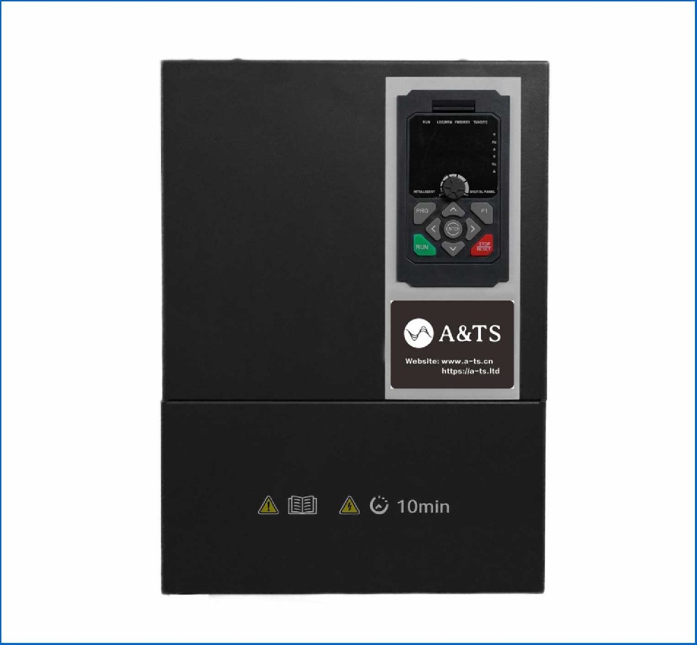
Spindle Drive | 11kW Vector Control Inverter | Sensorless Vector Control (SVC) / Closed-Loop Vector | Modbus RTU / 0–10V Analog |
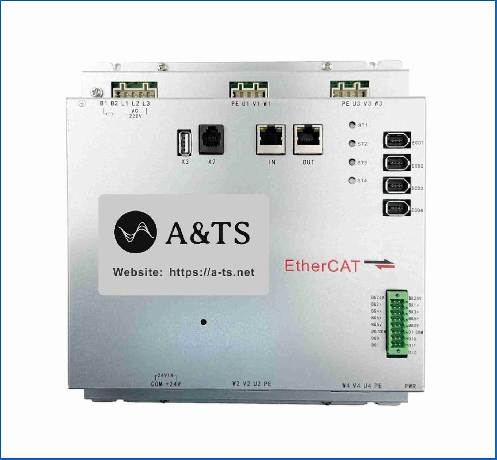
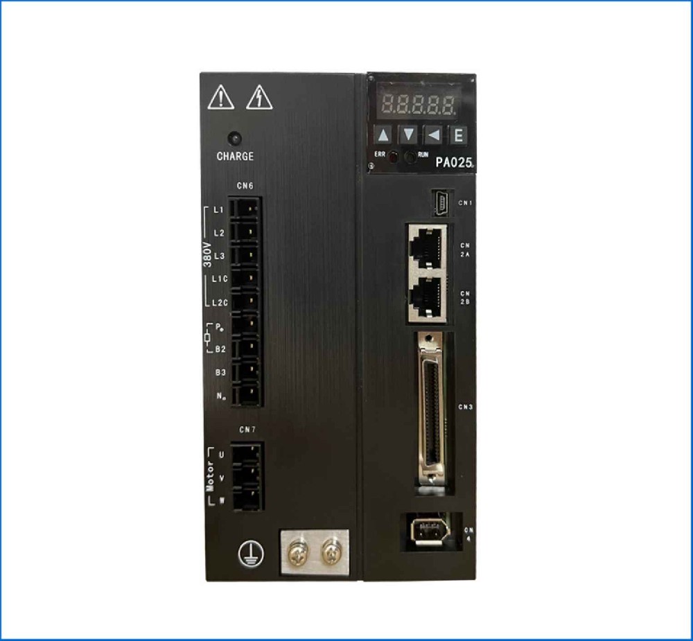
X/Z Axes Drives | 1.5 kW AC Servo Drives | Position Control Mode | Pulse + Direction (PTO) / EtherCAT |
CNC Controller | Multi-axis Motion Controller | Pulse / Bus Controller | Digital I/O & Bus Line |
Inverter Commissioning (Spindle Control)
The spindle requires high torque at low speeds for heavy cutting and rapid acceleration/deceleration to minimize dynamic cycle times.
1. Pre-Commissioning Checks
Verify line voltage matches drive rating (380VAC, 3-phase or 220VAC, 3-phase).
Ensure proper grounding of power supply and shielded motor cables to prevent EMI issues.
Connect external braking resistor to the dynamic braking terminal (P+ / PB).
2. Key Parameter Configuration
Parameter Function | Recommended Setting | Rationale |
Control Mode | Closed-Loop Vector / SVC | Maximize dynamic torque response under load changes |
Base Frequency | 50Hz-60Hz | Matched to motor nameplate |
Max Output Frequency | 120Hz / 200Hz | Provides extended constant power region for high-speed finish passes |
Accel / Decel Time | 1.5s / 1.5s | Fast transient cycles without triggering overvoltage/overcurrent faults |
Carrier Frequency | 8kHz - 12kHz | Reduces audible motor noise while balancing IGBT thermal loading |
Command Source | External Analog (0-10V) or Bus | Direct velocity scaling from CNC analog output |
3. Motor Autotuning & Testing
Perform Rotational Motor Autotune (decoupled from spindle load) to measure stator resistance, leakage inductance, and magnetizing current.
Ramp spindle to maximum speed and execute sudden step load changes to verify torque compensation accuracy.
Execute emergency stops at maximum RPM to ensure dynamic braking dissipates energy without triggering an OU (Overvoltage) alarm.
Servo Commissioning (X & Z Axis Feeds)
The feed axes demand high positioning accuracy, zero backlash compensation, and high dynamic stiffness to maintain precise contouring tolerances.
1. Wiring & Safety Verification
Connect 20-bit or higher incremental/absolute encoder cables with twisted-pair shielding.
2. Key Parameter Setup
Parameter | Value / Setting | Description |
Control Mode | Position Mode | External pulse generator controls position loop |
Electronic Gear Ratio | N/D adjusted to lead screw | Map controller pulses directly to physical movement |
Command Filter | FIR Low-Pass Filter | Smooths step inputs and limits mechanical shock |
Over-travel Limits | Software Limits Enabled | Prevents hard mechanical end-stop crashes |
3. Servo Loop Tuning Process
[Auto-Tuning / Inertia Estimation]
│
▼
[Position / Velocity Loop Gains]
│
▼
[Notch Filters (Resonance Suppression)]
│
▼
[Feedforward Tuning (Tracking Accuracy)]
Step 1: Inertia Estimation & Auto-Tuning Run auto-tuning routines to measure load-to-motor inertia ratio. Set initial loop gains based on calculated load stiffness.
Step 2: Resonant Frequency Suppression Perform Frequency Response Analysis (FFT) via servo software STP during rapid traverse. Identify mechanical resonance peaks (typically 200-800 Hz) and engage Adaptive Notch Filters to suppress high-frequency chatter.
Step 3: Gain Adjustment
Increase Velocity Loop Gain until rigidity is achieved without motor hum or excessive current oscillation.
Increase Position Loop Gain to reduce position error during contouring.
Adjust Velocity Integral Time Constant to eliminate steady-state position droop.
Step 4: Feedforward Tuning Apply Velocity Feedforward (80%–95%) to reduce phase lag during multi-axis interpolated motion (e.g., circular arc cutting).
Final System Verification
No-Load Running Test: Jog all axes manually; verify direction, pitch scaling, and soft limit triggers.
Circular Interpolation Test: Perform a 2-axis circular interpolation test at various feed rates and check quadrature error spikes or quadrant bumps using an oscilloscope or ballbar tester.
Full-Load Machining: Perform heavy roughing cuts to check spindle motor load percentage and verify that feed axes maintain stiffness under high cutting forces.